ESD Epoxy Flooring for Data Centers and High-Tech Facilities

Footwear and floor are tested together as one grounding system — qualified shoes on a static-dissipative epoxy floor (illustrative rendering)
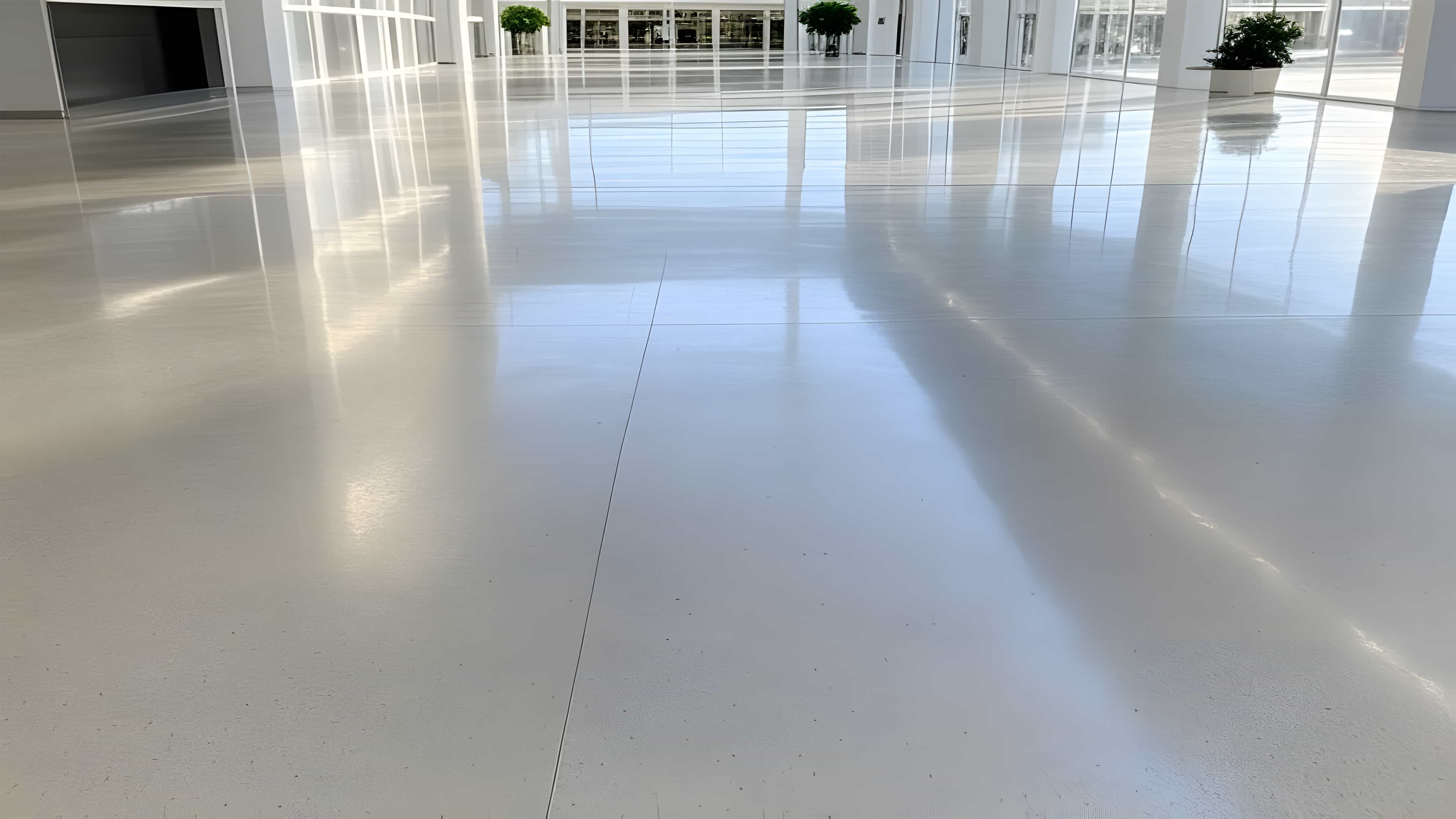
An ordinary gray epoxy floor and an ESD floor can look identical. The distinction is electrical: static-control media in the resin, manufacturer-designed grounding components, and a measured path from the traffic surface to an approved ground. Color and gloss reveal none of that. The submittal defines the assembly, and the closeout test report shows whether it performs.
That performance matters wherever sensitive electronics are unpacked, assembled, tested, repaired, or operated. The ESD Association explains that many components can be damaged below 100 volts; some disk-drive components have withstand levels below 10 volts. Those events are far below the level a person would feel, and the resulting damage may appear immediately or as a latent failure later.
A successful floor needs a specified resistance range, a verified ground path, compatible footwear or caster contact when people or carts use the floor for grounding, and documented testing. The room’s function determines the criteria. This guide covers the decisions we coordinate with owners, engineers, manufacturers, and electrical contractors on ESD flooring installations.
Start With the Room, Not the Product
A data center contains spaces with different risks. Hardware may be exposed in a staging or repair room, enclosed in racks in a live data hall, or absent from a mechanical room. ESD flooring is most relevant where sensitive devices are handled and the owner has included the floor in the ESD control program. Other rooms may place moisture, chemical exposure, impact, dust control, or battery hazards ahead of personnel grounding.
| Area | Question to resolve | Likely direction |
|---|---|---|
| Staging, burn-in, repair, and integration | Will technicians unpack, open, test, or repair sensitive hardware? | Strong candidate for a verified floor/footwear system |
| Data hall or server room on concrete | Does the owner or equipment provider require static control? | Resinous ESD system when the project criteria require it |
| Raised-access data hall | How are the finish and metal support structure grounded? | Static-control panels or finish with separately designed bonding |
| Electronics manufacturing or test laboratory | Is the room an ESD Protected Area under S20.20? | Formal qualification, grounding, and ongoing verification |
| UPS or battery room | What chemical, containment, fire, and electrical hazards govern? | Select from the complete hazard analysis; ESD is not automatic |
| Mechanical rooms, offices, and general storage | Are static-sensitive devices exposed or handled? | Conventional durable flooring unless the project says otherwise |
Owner standards illustrate why the room criteria come first. The VA Infrastructure Standard for Telecommunications Spaces specifies ESD or static-dissipative finishes in covered spaces and requires floor coatings to connect to the room’s Secondary Bonding Busbar. It separately addresses access-floor pedestal bonding under ANSI/TIA-607-D, code, and the authority having jurisdiction.
One IBM site-planning guide uses a different envelope for the equipment it covers: no more than 2 × 10¹⁰ Ω between the floor and the building or applicable ground reference, and no less than 150 kΩ between floor points 1 m (3 ft) apart. Those values answer a different question from the S20.20 footwear/flooring limits. The measurement geometry and governing document belong beside every resistance number.
Related room-selection guidance appears in our manufacturing-facility flooring overview and healthcare and laboratory flooring guide.
How the Floor, Footwear, and Ground Work Together
Walking, rolling a cart, and separating packaging can transfer electrons between surfaces. The floor controls that charge only when the complete path works. Insulating shoes can isolate a person from a compliant floor, just as nonconductive casters can isolate a cart. In a case described by Dr. Jeremy Smallwood, acceptable footwear and floor readings still produced excessive combined resistance and walking voltage because contact resistance dominated the circuit.
The installation and operating plan therefore need four connected elements:
- A floor resistance class selected for the facility’s ESD control plan.
- Manufacturer-required grounding media connected to a verified project ground.
- Qualified footwear and casters wherever the floor grounds personnel or mobile equipment.
- Floor and system testing under the methods named in the acceptance criteria.
Server racks, raised-floor structures, cabinets, and process equipment still need their own electrical bonds. An ESD floor also cannot neutralize every charged insulator in a room. It is one engineered control within a larger program.
Conductive and Static-Dissipative Floors
ANSI/ESD STM7.1-2020 defines conductive flooring below 1 × 10⁶ Ω and static-dissipative flooring at or above 1 × 10⁶ Ω and below 1 × 10⁹ Ω. The ESD Association’s public summary of the 2020 revision explains the boundary change.
These are resistance classes, not quality grades. A project may add a lower safety limit or a narrower operating range. “Anti-static” supplies too little information for acceptance unless it is accompanied by a resistance range, test method, grounding detail, and pass/fail criteria. Standard epoxy should not be assumed to provide an ESD path.
Standards and Acceptance Criteria
ANSI/ESD S20.20 establishes the control program; it does not approve individual coatings. Separate documents cover floor resistance, the person/footwear/floor path, walking voltage, grounding, and recurring verification. A construction specification should identify the method, edition, required result, test conditions, and responsible party.
| Document | What it covers | How it should be used in a flooring project |
|---|---|---|
| ANSI/ESD S20.20-2021 | Administrative and technical requirements for an ESD control program | Establishes the facility program and performance framework; it is not a product approval |
| ANSI/ESD STM7.1-2020 | Resistive characterization of flooring systems before and after installation | Used for floor qualification, acceptance, and monitoring measurements |
| ANSI/ESD STM97.1-2025 | Resistance through a person, the selected footwear, the floor, and ground | Proves that the actual personnel-grounding combination has a continuous path |
| ANSI/ESD STM97.2-2016 | Voltage generated on a person walking with the selected footwear and floor | Proves that the combination controls body voltage in motion |
| ANSI/ESD S6.1-2019 | Establishing, verifying, and maintaining ESD grounding and equipotential bonding | Guides the ESD ground/bonding design and verification |
| ESD TR53-01-22 | Compliance-verification procedures and troubleshooting for ESD controls | Supports the facility's recurring compliance-verification plan after construction |
| ASTM F150-25 | Electrical resistance of conductive and static-dissipative resilient flooring | Relevant when the specified material falls within its resilient tile/sheet scope; it should not automatically replace STM7.1 for a poured resinous floor |
We checked these editions against the ESD Association’s document-status list dated February 5, 2026. S6.1, STM7.1, and STM97.2 were under revision with publication estimated in 2026, and the next S20.20 edition was estimated for 2027. Confirm the current edition before you write any of them into a specification.
When a footwear/flooring system is used to ground personnel, the ESD Association’s basic control guidance sets two limits, and both must be met:
- Resistance from the person through the footwear and floor to ground: < 1 × 10⁹ Ω, tested under ANSI/ESD STM97.1.
- Peak body voltage during the walking test: < 100 V, tested under ANSI/ESD STM97.2.
A floor data sheet showing < 1 × 10⁹ Ω establishes neither. Footwear, contact resistance, cleaner residue, environmental conditions, and the installed ground path all move the combined number.
The Floor Is a Complete Resinous System
A poured ESD floor begins with evaluated and mechanically prepared concrete. The approved build may then include a compatible primer, conductive plane, grounding tape or mesh, a static-control body coat or slurry, and an ESD wear surface. Layer order, coverage, thickness, and cure windows come from the selected manufacturer. An ordinary repair material, moisture primer, or clear coat can interrupt the electrical path even when the finished floor looks uniform.
A Real Example: Sherwin-Williams Resuflor Topfloor SL12 SD
The system that prompted this article is a good example of a high-build static-dissipative assembly. Here is what the current Sherwin-Williams product page and May 2026 application instructions publish:
| Published requirement | Resuflor Topfloor SL12 SD example |
|---|---|
| Electrical class | Static dissipative; instructions use 1 × 10⁶–1 × 10⁹ Ω per 3 ft, so the project must reconcile boundary values and the test method |
| Minimum system thickness | 1/16 inch |
| Concrete preparation | CSP 4–6 |
| Conductive primer | Resuflor Aqua 3424; field check below 150,000 Ω under NFPA 99 before continuing |
| Ground coupling | Conductive strip, mesh, wire, or tape over the primer layer, connected to permanent earth ground per the approved detail |
| Slurry body | Resuflor 3564 with 5305 Static Dissipative Aggregate; average resistance below 1 × 10⁹ Ω under NFPA 99 before the seal coat |
| Wear surface | Published default: Resutile SDS Satin static-dissipative urethane topcoat; the instructions direct users to the Topcoat Selection Guide for alternatives |
| Published cure reference | Light traffic after 24 hours at 75°F and 50% RH; full coating properties develop in 7–14 days |
The instructions use 2.5 × 10⁴–1 × 10⁶ Ω per 3 ft for conductive flooring and 1 × 10⁶–1 × 10⁹ Ω per 3 ft for static-dissipative flooring. They also state a 25,000 Ω NFPA minimum. Those boundaries do not exactly match current STM7.1 terminology, so the owner’s specification must resolve the controlling limits, endpoint treatment, and measurement configuration.
Sherwin-Williams specifies its intermediate field checks under NFPA 99, while its measurement guide also names ASTM F150 and the superseded ANSI/ESD-S7.1 designation. An owner may require current STM7.1, STM97.1, and STM97.2 at acceptance. Before installation, the team should reconcile electrodes, voltage, timing, test locations, and pass/fail limits across those documents.
These values belong to Topfloor SL12 SD. They should not be carried into another system, and Sherwin-Williams requires approved contractors to contact technical service before application. The current instructions, project submittal, grounding drawing, and field QC plan need to describe the same assembly.
For the wider comparison across resinous chemistries, traffic levels, and operating constraints, see our industrial floor-coating service overview alongside the project-specific ESD criteria.
Grounding Is a Defined Project Handoff
Our completed ESD-floor installations have reinforced the importance of one handoff: the flooring crew installs the manufacturer-required conductive layers, grounding media, and protected leads, while the project documents identify the approved ground and assign the final connection. The electrical contractor commonly verifies the designated building ground and completes the bond when that work is in its scope. Any different division should appear in the approved submittal before flooring begins.
For Topfloor SL12 SD, Sherwin-Williams states: “It is absolutely critical that a true earth ground is established and that a reference ground not be used.” The approved electrical and ESD design determines that connection. The manufacturer’s statement does not authorize the flooring installer to select a convenient ground.
ANSI/ESD S6.1 addresses the ESD grounding and bonding system. The Association has explained that its guidance reaches the building electrical system’s main ground; design and testing beyond that boundary belong to the electrical discipline and NFPA 70.
A practical sequence is:
- Approve the ESD flooring system, shop drawing, ground locations, and division of work.
- Have the electrical contractor verify the designated grounding points.
- Prepare the slab and install the primer and grounding media in the manufacturer’s sequence.
- Complete the specified intermediate checks and final ground connections.
- Install the remaining layers, allow the required cure, and perform acceptance testing.
A floor lead should never be attached to structural steel, piping, a receptacle, or a separate rod without an approved electrical detail. The floor connection also does not bond racks, cabinets, raised-floor structures, or equipment; those remain separate electrical scopes.
Discuss Your ESD Flooring Scope
We install manufacturer-specified conductive and static-dissipative resinous systems, including surface preparation and grounding media. We also coordinate the electrical handoff and acceptance-testing scope. Licensed Florida Professional Engineer on staff. Serving Florida and the Southeast.
Installation Quality Controls
An ESD floor can miss its electrical criteria for familiar coating reasons: an untested slab, inadequate preparation, uneven filler dispersion, stretched coverage, an incompatible repair or topcoat, damaged grounding media, or testing before full cure. Electrical performance adds checkpoints to the installation; it does not replace normal resinous-flooring discipline.
Concrete, Moisture, and Repairs
Test the concrete before final system selection. ASTM F2170 measures relative humidity inside the slab; the result must be compared with the selected system’s limit. Moisture mitigation, patches, joint materials, and repair mortars require manufacturer confirmation because a compatible-looking product may change adhesion or electrical continuity.
Surface preparation is system-specific. Topfloor SL12 SD calls for CSP 4–6, while a thinner coating may use another profile. Existing coatings, curing compounds, contamination, laitance, and unsound concrete must be removed or remediated before the approved repair details are installed.
Mixing, Coverage, and Cure
Conductive and static-dissipative fillers must remain uniformly dispersed. Do not split premeasured components or stretch material beyond the published coverage. Record batch numbers, mix times, coverage, and environmental conditions. Final testing belongs after the specified cure, which may be later than the light-traffic milestone, and before an unapproved cleaner or finish changes the surface.
Acceptance Testing and Closeout
Acceptance testing maps resistance to ground and across the surface. When the floor grounds personnel, it also evaluates the actual footwear/floor combination and walking body voltage. The owner’s specification establishes the number and distribution of readings.
| Verification | What it checks | Common governing document |
|---|---|---|
| Resistance to a groundable point | The path from the floor surface through the assembly to its designated ground | ANSI/ESD STM7.1 |
| Point-to-point floor resistance | Electrical consistency across the installed surface | ANSI/ESD STM7.1 |
| Person/footwear/floor resistance | The complete path through a person wearing the actual approved footwear | ANSI/ESD STM97.1 |
| Walking body voltage | The charge generated while a person walks on the actual footwear/floor combination | ANSI/ESD STM97.2 |
| Grounding/bonding verification | Continuity and integrity of the ESD ground and bonding network | ANSI/ESD S6.1 and the electrical drawings |
For recurring program checks after construction, ESD TR53-01-22 supplies compliance-verification procedures and troubleshooting guidance for ESD protective equipment and materials. The owner’s compliance-verification plan may be stricter.
At minimum, the acceptance report should capture:
- Project, room, grid, test location, configuration, and each individual reading.
- Date, time, temperature, and relative humidity.
- Meter, electrode, applied test voltage, timing, and calibration status.
- Ground point used and confirmation that it was verified.
- Flooring system, lot information, cure condition, and any cleaner or surface treatment.
- Footwear manufacturer, model, condition, and wearer for system tests.
- Pass/fail criteria, corrective action, and retest results for nonconforming locations.
Large-area test plans should include perimeters, joints, repairs, transitions, ground locations, and representative traffic lanes. Baseline results at turnover give the facility a useful comparison for later verification.
Humidity, Cleaning, and Periodic Verification
Humidity affects charge generation and material resistance, but it is not the primary control under S20.20. The ESD Association humidity FAQ states that control items are qualified at 12% ± 3% RH and 23°C ± 3°C and must work at the facility’s lowest experienced humidity. Below 9% RH, function should be verified at the actual low condition.
Data-center environmental requirements still apply. The IBM guide cited earlier, for example, recommends a control point that normally maintains 35% to 60% RH within the server operating limits. Humidity control complements the ESD system rather than replacing its floor, footwear, and grounding checks.
Cleaning also changes electrical performance. Wax, polish, soap film, hard-water residue, dirt, and unapproved repair coatings can increase contact resistance. The Sherwin-Williams maintenance guide calls for compatible cleaners and residue-free procedures. The facility plan should include:
- Approved cleaner, dilution, pad or brush, rinse, and recovery method.
- No conventional wax, finish, polish, sealer, or topcoat unless the ESD-system manufacturer approves it in writing.
- Baseline tests at turnover and periodic tests at the frequency the ESD control plan establishes.
- Additional testing after deep cleaning, repairs, recoating, contamination, or footwear changes.
- Location-based records for high-traffic and historically unstable areas.
NASA’s 2010 baseline ESD workmanship handbook likewise calls for grounded flooring, appropriate personnel grounding, and resistance verification after maintenance. Its cited test editions are older, so the current project documents govern the procedure.
What a Bid-Ready ESD Flooring Specification Needs
“Provide anti-static epoxy flooring” leaves the electrical result undefined. Pricing becomes more reliable when the project team resolves these eight items:
- Controlled areas and purpose: Which rooms need static control, what sensitive items are present, and is the floor grounding personnel, carts, equipment, or some combination?
- Standards and acceptance: Governing editions, floor class, minimum and maximum resistance, test configurations, and any walking-voltage limit.
- Footwear and mobile equipment: Approved shoe, heel-grounder, caster, or wheel combinations and who qualifies them with the installed floor.
- Grounding design: Ground type, approved connection points, tape/mesh layout, number and location of leads, testing, accessible terminations, and division between flooring and electrical work.
- Substrate criteria: Concrete age and condition, moisture test and limit, contamination, surface profile, repairs, joints, vapor mitigation, and compatibility letters.
- Complete system and service conditions: Named components, layer order, thickness, cure, color, texture, traffic, impact, chemicals, temperature, and cleaning requirements.
- Quality control: Manufacturer-approved installer, preinstallation meeting, mockup or test area, intermediate resistance hold points, environmental records, batch records, and manufacturer field support.
- Testing and closeout: Test density and locations, methods, equipment, responsible party, report format, retest procedure, training, approved cleaners, and verification schedule.
Proposal language should point to submittal evidence. “Meets ANSI standards” should identify the standard and limit; “ground as required” should point to an approved detail; and “final testing included” should name the test plan, instruments, report, and corrective process.
ESD Flooring Scope Review and Installation
Advance Industrial Coatings installs conductive and static-dissipative resinous flooring for data centers, electronics facilities, and other controlled environments across Florida and the Southeast. Our flooring work includes slab evaluation and preparation, manufacturer-specified grounding media, the complete resinous assembly, and the installation QC assigned to our scope. We coordinate the electrical handoff and acceptance testing with the project team.
For pricing, send the room list, square footage, slab information, specification, and schedule. If the documents leave a resistance, grounding, footwear, or testing question unresolved, we identify it before mobilization and coordinate a documented answer with the engineer, electrical contractor, and manufacturer.
Get a Quote for Your ESD Flooring Project
Send us the room list, square footage, slab information, specification, and schedule. We'll review the system, installation scope, grounding handoff, and acceptance requirements before pricing.
Frequently Asked Questions
Is ESD flooring the same as conductive flooring?
No. ESD flooring is the broader category. A floor may be conductive, meaning below 1 × 10⁶ Ω under the current ANSI/ESD STM7.1 floor definition, or static dissipative, from 1 × 10⁶ Ω up to but not including 1 × 10⁹ Ω. The facility's ESD control plan determines which class fits and whether additional limits apply.
Does ordinary epoxy flooring control static electricity?
Not unless it was engineered and tested for it. A standard epoxy floor can be durable, seamless, and dust-resistant without offering any specified electrical path. An ESD resinous floor combines static-control resins or fillers, grounding media, compatible layers, and an acceptance test, and none of that shows in the color or the gloss.
Does an ESD floor work with regular shoes?
The floor keeps its own measured resistance, but it can't reliably ground a person through insulating footwear. When personnel grounding is part of the design, the actual footwear/floor combination has to meet the project requirements for person-to-ground resistance and walking body voltage, and each footwear type should be qualified with the selected floor.
How many grounding connections does an ESD floor need?
There's no universal number worth copying. The manufacturer, electrical engineer, ESD coordinator, room geometry, system type, and project standard together determine the quantity, spacing, location, and termination. Those details belong on an approved shop drawing before installation, not in a field decision after it.
Who installs and connects the grounding tape?
The resinous-flooring contractor typically installs the tape, mesh, wire, and leads embedded in the floor system. The electrical contractor typically verifies the designated building ground and makes the final electrical bond. Spell out the exact division in the drawings and specifications, because practices and licensing requirements vary by project and jurisdiction.
Can ESD epoxy be installed over an existing coating?
Sometimes, but only when the manufacturer approves the complete condition and assembly after evaluating adhesion, contamination, moisture, existing-system compatibility, thickness, transitions, and electrical continuity. Many projects end up removing everything down to sound concrete. An ESD topcoat over an unknown coating is not automatically a compliant ground path.
How often should an ESD floor be tested?
At installation acceptance, then at the frequency the facility's ESD control and compliance-verification plan establishes. Retest after repairs, recoating, relevant maintenance, unusual contamination, or a change in footwear. High-traffic lanes and historically unstable areas deserve targeted trend measurements.
What does ESD epoxy flooring cost?
There's no responsible square-foot number without the electrical criteria and slab conditions in hand. Cost rides on system thickness, conductive versus dissipative performance, concrete preparation, moisture mitigation, repairs, grounding layout, cove and transitions, work phasing, manufacturer field support, and acceptance testing. Expect it to run above a visually similar conventional coating, because the complete system and the proof of performance are part of the work.
ABOUT THE AUTHOR
Tony Guan, Ph.D., P.E. is the founder and owner of Advance Industrial Coatings. He is a licensed Florida Professional Engineer (license #72447) and SSPC QCS-certified coatings specialist, with engineering and field experience across commercial floor-coating and concrete-polishing installations in food processing, healthcare, manufacturing, and institutional facilities throughout Florida and the Southeast. For scope review or specification assistance, contact AI Coating directly.
Related Reading
Industrial Floor Coating
Heavy-duty epoxy, urethane mortar, novolac, MMA, and ESD flooring systems for industrial facilities across Florida.
Continue reading →IndustryManufacturing Facility Flooring
Room-by-room flooring systems for manufacturing environments — chemical exposure, forklift traffic, and static-sensitive production areas.
Continue reading →BlogHealthcare Facility Flooring
What CDC, Joint Commission, USP 797/800, and ISO 14644 mean for healthcare flooring — infection control, cleanroom compounding, and how to specify it.
Continue reading →